

House in the Woods
On a recent project with mwworks, the workload consisted of many forms of concrete, from foundation pours to flatwork to highly custom features, including a concrete Ring Beam, 30-foot-tall concrete stacks, and a concrete Seep Wall embedded with cut stones. For our latest Field Notes, Fieldworks Partner and Superintendent, Rene Cruz Garcia, discusses the technical aspects, collaboration process, and execution for these bodies of work.
Ring Beam
The Ring Beam is a concrete architectural element used to terminate primary structure and roofing assemblies and was created using custom-milled boards of various widths and thicknesses for varied appearance and relief on the surface. Intentional gaps were left between the form for concrete icing to seep between, leaving fractured fins behind that were further distressed by the architect for the desired weathered aesthetic.

What was the mock-up process like for the Ring Beam?
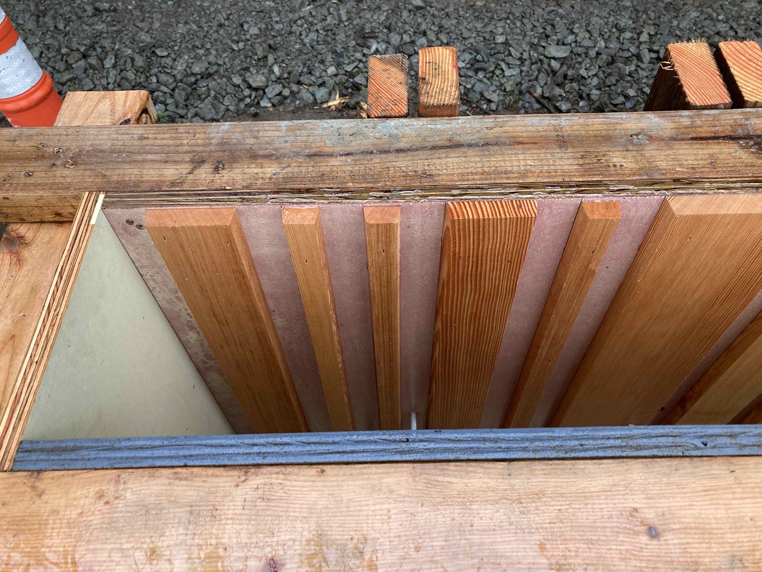
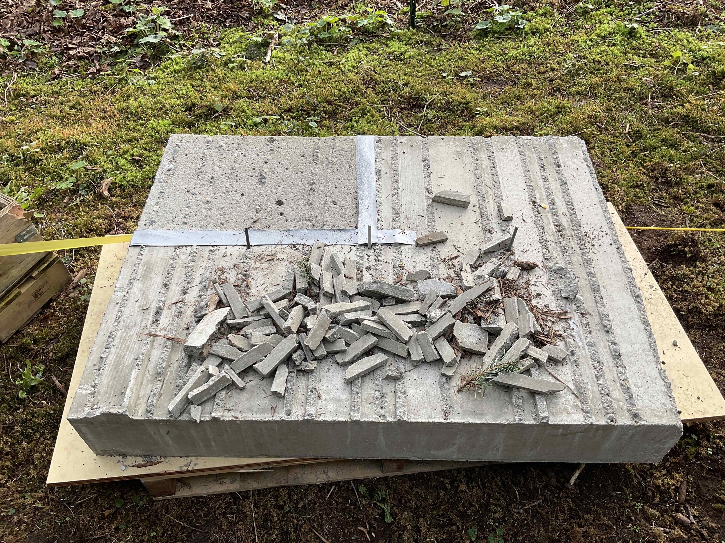
Our team built two mock-ups on site—both handcrafted forms. Using cedar for the Ring Beam pattern, the edges of the boards were beveled and stapled onto the face of an HDO panel to create the grooved relief pattern present on the face of the Ring Beam. Spacing between the ridges and groovers were 3/4”, 1”, 2”, 4”, and 5” in a repeating pattern. Both mock-ups were 4’ x 4’ wide x 6” thick. A normal vibrating cadence was used while the team poured the mock-ups. The first mock-up used a typical mix, and upon removal of the forms, many of the proud ridges broke off. For the second, we used a typical wall mix with fiber mesh added to enhance the strength of the ridges and found success.


Was the form process for this scope a challenging one?
The form process for the Ring Beam was a challenge that required strategic problem-solving for several reasons.
First, our team had to navigate the creation of a form for a one-sided scope of work that must securely attach to the structural steel fascia beam. The fiberglass rods and grippers used for the Ring Beam needed to be welded onto the structural fascia beam before our team could start the forming process—a very atypical sequence of work, since ring beams are a rare occurrence except for other notable architectural works. The forming is unique because it does not utilize typical forming methods where formwork is easily accessed from both sides. It is similar to a one-sided forming method used on shoring conditions where the backside of the form is inaccessible. Grippers were installed once both sides of the wall panels were up and worked as removable hardware that fastened onto the fiberglass rods to support the formwork and prevent it from bulging during a pour, keeping the wall plumb and straight.


Additionally, our team designed and built a shoring platform to support the exposed underside of the Ring Beam. The shoring needed to support the weight of the Ring Beam during the pour, as well as for the 30 days that the shoring must remain until the Ring Beam has reached full compression strength. Another challenge was achieving an architectural finish on the underside of the exposed Ring Beam. New HDO panels were used on the bottom face for a smooth, clean appearance.

Lastly, waterproofing considerations were an important driver for our forming methods. A highly intricate detail was developed by the general contractor and vetted with all parties to ensure design intent was intact while forming methods were achieved and waterproofing strategies were left in a resilient state with a high level of performance. This is a classic example of modern detailing that is made to look simple, yet has layers of complexity that excited the entire project team. In essence, it was formed as a partial one-sided wall where waterproofing pathways had to be preserved through intensive waterproofing methods as they related to the reinforcement and forming methods used to build the ring beam. From beneath, there is a seemingly simple drainage plane that is bifurcated—draining water out of the assembly and preserving air passage to an adjacent soffit condition. All components, save a flashing at the end, had to be placed within the formwork before the pour and tolerances had to be maintained to preserve and keep the functionality of the entire system intact. None of the functionality of this system will ever be seen and what will remain is the indelible mark of thousands of pounds of thoughtfully placed levitating concrete.

What did collaboration look like between Fieldworks and the design team?
There were many meetings on-site to coordinate with the architect and general contractor throughout each step of the process. Because we had the shoring plan engineered, we were able to walk the site with the shoring vendor to ensure that all needs were being met. After the Ring Beam was poured and stripped, the design team wanted to achieve a more weathered look on the face of the Ring Beam—we gave them a few hammers, supervised to make sure the distressing didn’t go too far, and let them hammer away at some of the ridges!

Concrete Stacks
Four concrete stacks standing over thirty feet tall are featured throughout the project, providing the structure for an outdoor fireplace, living room fireplace, kitchen ventilation stack, and bedroom fireplace. Key to all was the way they were used as pathways to eliminate any and all conventional penetrations for normalized pathways for plumbing and other mechanical penetrations in roofs. This residence has no penetration within the primary roof structures, and this was intentional and relied heavily on the existence of these concrete stacks for primary pathways.


What factors were considered for the desired outcome of the concrete stacks?
The design team looked at a wide variety of mockups and concrete mix samples for the concrete stacks. Lift lines were studied along with textures, forming methods, sandblasting, and different approaches to obtain the ideal outcome based on numerous considerations. Form panels were spliced using a CNC to take standard 10’ panels and lengthen them to avoid a butt joint.


What were the most crucial components of a pour this tall?
Solid scaffolding was a crucial component of this pour, ensuring our team was provided with sturdy, secure locations at all heights. Tilt-up braces were also utilized—typical in industrial concrete work, the braces support the weight of tall panels during construction and ensure they remain securely in place. For the concrete stack forms, we maxed at 40 feet and used a forklift to lift the tilt-ups in place. We formed the walls, closed them up, and then installed the braces.

What did the form process and pour sequence look like?
We formed the inside of the stacks first using 1 1/8-inch HDO panels and braces. We then closed the stack with new 3/4-inch HDO panels, fiberglass rods, grippers, 2x4 vertical strong backs, 2x4 horizontal walers, and plenty of braces. Every exterior panel was custom length and width. Each panel had to be touched twice with a saw, due to the staggered aesthetic of the panel seams that produce a patch-like appearance. All ties were aligned from top to bottom and side to side per the design.
Three pours were required for all the interior stacks, but our team was able to pour the exterior fireplace stack in two pours. The pours consisted of 8-to-10-foot-tall lifts per pour. For the exterior fireplace stack, we poured an 8-foot lift in the first pour and then were able to pour the remaining height—plus or minus twenty feet—for the second pour. A few of our vibrator whips had to be extended in length. Typically, we use a 16-foot whip for tall walls, but for the height of these stacks, we needed to increase the length of the whip to 25 feet.
Were there any other special considerations for this pour?
Another primary consideration for the three interior stacks was thermal breaks that existed to match the rake of the roof and in some instances ran vertically. This was a significant consideration for the performance of the building in that it mitigated the ability of the cold at the exterior to migrate into the interior of the home. Our team had to facilitate the work, which consisted of a 1-inch-thick piece of structural plastic placed between the pours, made by a company called Armatherm. This solution was a great success because of the level of collaboration between Fieldworks and the general contractor.
Beneath the waterproofing, there is the Armatherm thermal break. Each piece of rebar penetrates the Armatherm and must be waterproofed. There is also a piece of flashing integrated into this assembly to prevent any condensation or water from entering the interior of the structure.

Seep Wall
The Seep Wall is an architectural feature that integrates stacked boulders and concrete for a finished appearance where the concrete wall appears to form around the rocks.
What did the form process look like for the Seep Wall?
There were two phases of formwork for the Seep Wall. First, we formed a wall that the large boulders would sit on. The second phase involved building the rest of the Seep Wall around the rocks, achieved first by cutting angles into the panel that closely followed the rock shape by hand. Next, we used a tiny washer and a pencil to scribe along the rock edge on the panel to outline the actual rock shape. From there, a jigsaw was used to cut along the scribe—typically, we never need to use a jigsaw when we form. Finally, we were able to set the custom-cut panels snuggly on top of the boulders and close the wall. Because it was one-sided, our team had to drill and epoxy the fiberglass rods into the existing house wall.

What were the special considerations for this unique scope of work?
The Seep Wall finish needed to match the existing walls, which were sandblasted. To eliminate the need to sandblast the Seep Wall, our team used an in-form acid retarder to etch the face of the wall with a chemical reaction that keeps the concrete from curing—achieving the sandblasted effect. This product was not used anywhere else on the site but achieved the desired appearance. The space around the Seep Wall is glass and cedar, so the challenge was to reduce any damage to the finish surfaces. Using the acid retarder eliminated the need for the general contractor to sandblast around all the finished exterior materials and reduced the risk of damage to those surfaces.


